
Board stack-up and assembly
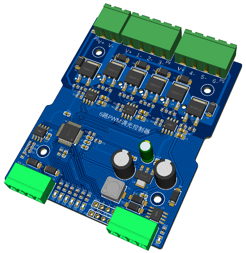
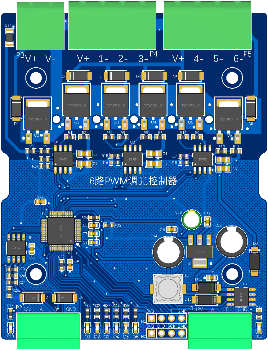
Depending on signal density and load current we use 2, 4 or 6-layer boards: dense signal routing, high-current copper paths, high-temperature component selection and EMC layout are decided together, not sequentially. Standard terminal blocks, SMT assembly, secure component retention and transport robustness are treated as design requirements because the module is installed by an electrical contractor, not by the engineer who drew it.
Electrical stress targets
The following are design and verification targets used in our hardware development, not certification claims: EMC layout discipline; surge voltage 2500 V; electrical fast transient / burst 3000 V; strong-to-weak isolation 3500 V; ESD withstand 4000 V; surge current 80 A; and a relay service life target of 10,000 operations. Request the current datasheet for values applicable to a specific hardware revision.
Thermal design and enclosure reality
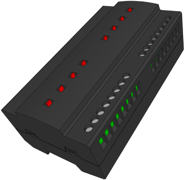
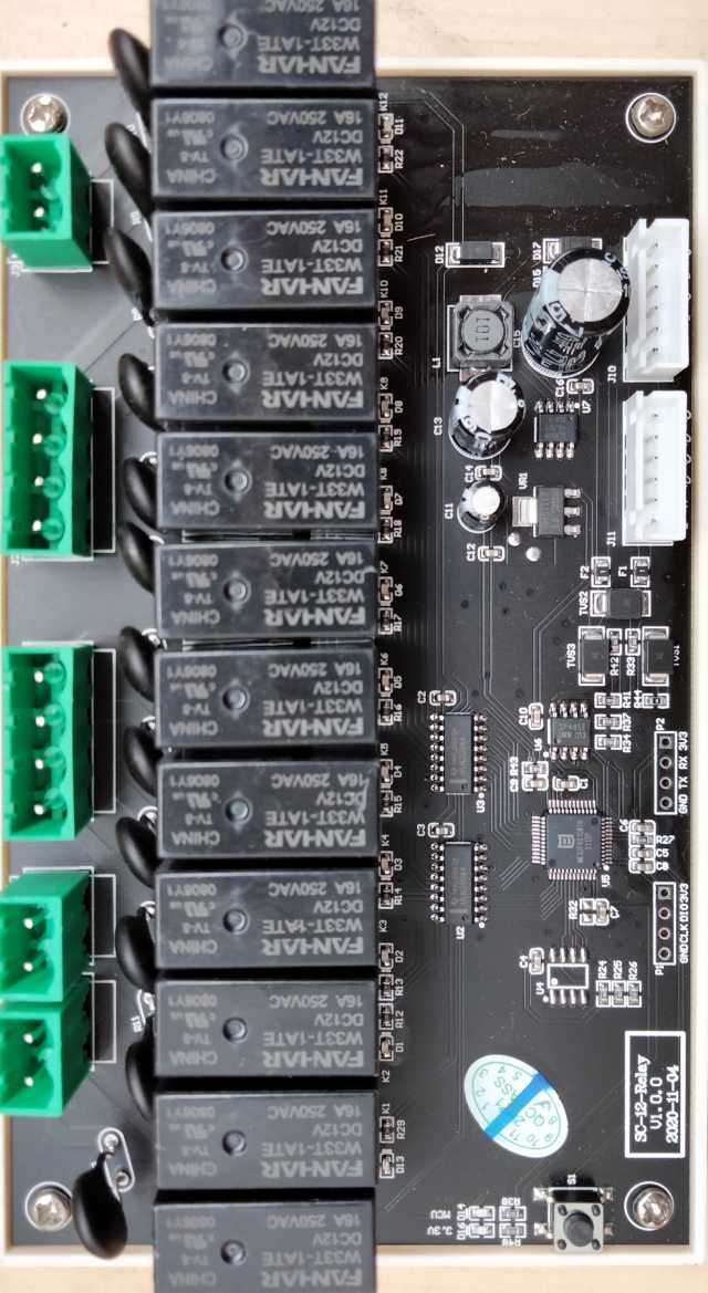
A twelve-channel relay module carries more current in one housing than three four-channel modules, so full-load temperature rise has to be calculated with the enclosure closed. Our central supply rule of thumb — keep loading near or below 70% and leave cooling clearance — comes from the same measurement. Over-temperature protection that trips in a summer guest room is a design failure, not a component failure.
Integration versus fault domain
A fusion box that combines RS-485, dry-contact IO, Ethernet and relays reduces the module count and simplifies wiring. The trade-off is a larger single point of failure, so we keep an independent backup circuit on high-integration designs. Where a room mixes motor, dimming and relay loads, separate modules remain easier to isolate and service in stages.
Sources and field note
These checks are compiled from HOTEKEY engineering commissioning notes written while specifying, wiring and troubleshooting guest room control hardware. Photographs show our own modules and enclosure layouts. Electrical stress figures on this site are design and verification targets used in hardware development; they are not certification claims. For project-specific values, request the current datasheet from our engineering team.
- Are the 2500 V / 3500 V figures certifications?
- No. They are design and verification targets used in hardware development, not certification claims. Ask for the current datasheet of the exact hardware revision for applicable values.
- Why use 2, 4 or 6-layer boards for different modules?
- Layer count follows signal density, high-current copper requirements and EMC layout. A dimming or multi-relay module needs different copper and isolation strategy from a simple panel board.
- Why does a 12-channel relay module need special thermal checks?
- All channels can be energised in one housing, so full-load heat is concentrated. Enclosure temperature rise must be calculated with the door closed, with cooling clearance left around the module.
- Is a fully integrated fusion box always better?
- It reduces module count and wiring, but one failure affects more circuits. We keep an independent backup circuit and split mixed motor, dimming and relay loads into separate modules for staged troubleshooting.